Tuesday, April 30, 2024

Develop a Vacuum Packaged Infrared Imaging Sensor Array

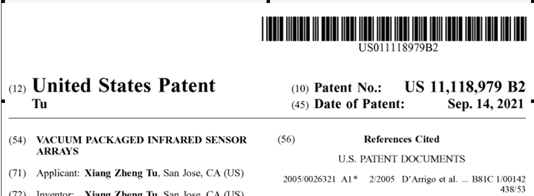
Utilizing US Patent 11,118,979 B2

Xiang Zheng Tu


A major advantage of infrared imaging sensors is their ability to detect living objects. They operate effectively in both day and night conditions and provide all-weather capability.

US Patent 11,118,979 B2 describes a wafer-level vacuum packaged infrared image sensor array with outstanding performance. Each pixel within the array includes a thermopile made from polysilicon silicon, which offers low resistance, minimal thermal noise, high integration, and heightened sensitivity. The vacuum enhancement in the packaged array is achieved through low-temperature oxidation of a porous silicon layer formed in the lid silicon substrate, which is then bonded to the infrared sensor array's silicon substrate. This process is driven by the reduction of surface energy in the porous silicon.

Wafer-Level Vacuum Packaging Process

The sensors are produced on a semiconductor wafer using materials such as silicon, indium antimonide, or mercury cadmium telluride, tailored to the application and required wavelength range.

Micro-Electromechanical Systems (MEMS) Integration**: Integration of MEMS technology with the sensors on the same wafer often includes micro-optical components like lenses and mirrors, as well as mechanical components such as actuators. 

Following fabrication, the wafer is encapsulated to create a vacuum seal. This usually involves bonding a cap wafer or a glass lid to the sensor wafer using methods like anodic bonding, fusion bonding, or adhesives compatible with the operational environment. 

The encapsulation process is followed by dicing the wafer into discrete units, each containing one sensor package.

Advantages of Wafer-Level Vacuum Packaging

This technique produces extremely compact sensor packages, ideal for space-constrained applications such as in mobile devices or compact electronics.

Simultaneous packaging of multiple sensors on a wafer scale significantly reduces manufacturing costs compared to packaging sensors individually.

The vacuum environment inside the package minimizes atmospheric gas interference and reduces thermal noise, thus enhancing the sensor's sensitivity and signal-to-noise ratio. This feature is crucial for thermal infrared sensors.

The sensors are well-protected against environmental factors such as humidity, dust, and chemical contaminants, which can degrade the sensor elements over time.

This manufacturing method is highly scalable, facilitating an increase in production without substantial cost increases.

Wafer-level vacuum packaging represents a significant advancement in infrared sensor technology, especially for applications demanding high reliability and precision, such as in aerospace, military, and advanced automotive systems, including autonomous driving.


Wednesday, March 21, 2018


Heating Temperature Accuracy Control for Unburned Cigarettes Based on POSIFA’s Thermal Flow Sensors

Xiang Zheng Tu


Unburned cigarettes are becoming popular because they have been proved to reduce the health risks significantly. It has been shown that when shredded tobacco sample is heated at 10 0C rate in nitrogen its weight loss curve delineates four regions: region I (30-1200C), related to the evaporation of water absorbed in the sample; region II (120-2500C), related to the emission of acetaldehyde, carbon dioxide, nicotine, and water; region III (250-3700C), related to the emission of acetaldehyde, carbon dioxide, nicotine, and more water; and region IV (370-5500C), related to the emission of more carbon dioxide and carbon monoxide.

A nicotine emission rate curve for the shredded tobacco sample is shown in the above figure. As can be seen, nicotine vapor is limited to form in the heating temperature range of 175 to 3500C. Since in this temperature range the tobacco is only heated but not burned it is impossible for the tobacco to emit any harmful chemicals such as CO, NO and NOx. At the heart of any unburned cigarette is a sophisticated electronic controller. With such a controller the temperature of the heater is controlled just in the predetermined range.

Again reference to the above figure an electronic controller is designed based on a POSIFA’s thermal flow sensor. The thermal water flow sensor is made up of two thermopiles and operated in conjunction with a resistive heater element for thermoelectric sensing. The mass flow rate of air passing through the thermal flow sensor is calculated on the basis of the measured temperature difference between the hot and cold junctions of the thermopile, and the thermal conductivity coefficient, electric heat rate and specific heat of air.

For air flow rate measurement the house of the unburned cigarette is selected to be a bypass configuration which has a main line and a bypass line. The thermal flow sensor is installed in the bypass line. The flow ration between the main line and the bypass line is determined in advance. Then the flow rate of the main line can be calculated by measuring the flow rate in the bypass line by the thermal flow sensor.

The output of the thermal flow sensor is sent to a microcontroller for digital processing and converted into a PWM signal used to modulate a heating voltage for heating the heater of the cigarette. The microcontroller also processes the output of a temperature sensor which is used to monitor the heated heater. The microcontroller is operated with a program so that the heater is heated up to 175 to 350°C, while monitoring the temperature to ensure a consistent taste experience for user and to avoid burning. It also has an over-heating protection function, which turns itself off if necessary.

In a traditional unburned cigarette a puff at 120 s usually create a sudden and significant temperature drop due to the cooling effect by incoming air. This temperature drop by puffing became less significant with the thermal flow sensor based microcontroller. This is because the longer puff can be detected by the thermal flow sensor and feedback to the microcontroller for providing higher heating voltage. Since any puff can be detected by the thermal flow sensor the switch function for applying electric power can be replaced by the puff itself. And the heating temperature also can be increased according to the strength of the puff so that the used more enjoy the real taste of the unburned cigarettes.

Tuesday, March 6, 2018


Smart House Water Consumption Systems

Xiang Zheng Tu


Our smart house water consumption systems are based on proven thermal water flow sensors. As shown in the above figure, the smart house water consumption system mainly consists of a variable frequency water pump, a house water filter, two POSIFA’s thermal water flow sensors and a smart phone.

A thermal water flow sensor is made up of two thermopiles, which is used as the sensing temperature difference element and operated in conjunction with a resistive heater element for thermoelectric sensing. The water mass flow passing through the thermal sensor is calculated on the basis of the measured temperature difference between the hot and cold junctions of the thermopile, and the thermal conductivity coefficient, electric heat rate and specific heat of water. Compare with other type of water flow sensors the thermal water flow sensors have the advantages as:
·       Thermal water flow sensors have no moving part and no any mechanical failures to take place.
·       Thermal water flow sensors are MEMS devices with small size, higher sensitivity, higher reliability, low power consumption, ease of fabrication, and low cost.
·       Thermal water flow sensors calculate mass flow rather than volumetric flow and do not require temperature or pressure correction, which means there is no additional expense for the purchase and installation of additional equipment.
·       Thermal water flow sensors provide excellent accuracy and repeatability over a wide range of flow rates using bypass flow tube design. The sensor is placed in a bypass around a restriction in the main pipe and is sized to operate in the laminar flow region over its full operating range. 
·       Thermal conductivity water flow sensors are not influenced by the air bubbles entrained in the water. The effect of the bubbles can be added to the series conductivity by using conductivity of the air-water mixture for the water conductivity. The thermal conductivity of continuous water phase with entrapped air bubbles can be calculated.

The variable frequency water pump is equipped with a viable frequency drive. The viable frequency drove is used to adjust the speed of an electric motor by modulating the power being delivered. It provides continuous control, matching motor speed to the specific demands of the water flow. This makes the pump more efficient and also saves the user money by reducing excess energy from being wasted. When a user implements the variable frequency pump benefits are experienced over the life cycle of the pump. On an average 85 percent of a pump’s life cycle cost is attributed to its energy consumption and only 15 percent the actual cost of the pump motor. Motors associated with pumps tend to be sized where the pump may to meet peak loads, but not necessarily for normal continuous operation. Typically, for every 1 percent reduction in the variable frequency drive output the user can save 2.7 percent of energy costs. As energy consumptions continue to rise, it will become more imperative to find ways to cut energy consumption. Variable frequency water pump application is a key aspect to this effort.

The variable frequency drive is controlled to maintain a constant water flow in the output pipe. The down thermal water flow sensor measures the flow rate in the pipe to the water service and as this change sends a signal to the smart phone, which in turn sends a speed demand signal to the drive and this in turn adjust the speed of the motor so that the water flow rate reaches the presetting value. 

The water flow date measured by the down thermal flow sensor can be reviewed and analysis by the smart phone. The screen of the smart phone displays variety of water flow readings including average, minimum, maximum water flow rate, and total water and energy consumption in a month or year. With these data users may understand exactly when, where and how much water they’re consuming in their home on a daily basis.

The water filter takes away impurities from water, like chlorine taste, odor, zinc, copper, cadmium, and mercury. There are several water filters for soft water filtration like activated carbon filters, reverse osmosis, alkaline water ionizers, UV filters, and infrared filters. These filters are inexpensive but they require frequent replacements. Replacing water filter depends on several factors. Water filters typically have an estimated life cycle. However, this is only a guideline based on average water use. This isn't always a good indicator since water use varies per user. Referencing to the figure, the up thermal flow sensor and down thermal flow sensor respectively monitor the input and output water flow rate of the water filter. When the drop in flow rate passes a predetermined value then it’s time to change the filter.

Tuesday, February 27, 2018


Constant Water Flow System with Thermal Water Flow Sensor and
Variable Frequency Pump

Xiang Zheng Tu


It has been reported that electrical energy consumed by pumps, fans and compressors represents a significant proportion of the electricity used around the world. It is estimated that in industrial processes and building utilities, 72 % of electricity is consumed by motors, of which 63 % is used to drive fluid flow in pumps, fans and compressors.

Many heating, cooling and ventilation distribution systems operate at a constant flow rate, even though peak demand may only be required for a few hours. The conventional response to meeting the changing demand for heating and cooling within a building is to restrict flow to individual rooms, while maintaining peak flow in the central system. However, through the use of this approach, considerable energy is used and equipment lifetime is shortened.

For saving energy a better approach is to use a variable speed drive on pumps and fans to vary air or water flow to meet more precisely changing load demands. As shown in the above figure, a constant water flow system comprises a variable frequency pump and a POSIFA’s thermal flow sensor. When the water flow decreases in the user pipe the thermal flow sensor measurement signal decreases. This signal feedback to the variable frequency inverter and results its output frequency decreased. With decreased frequency the operation speed of the variable frequency pump is also decreased and the water flow in the user pipe starts to drop back as to original balance. When the water flow increases the similar process will happen only the direction is opposite.

There is an everyday analogy that can help explain the efficiency advantage of a variable frequency pump.  Imagine you are driving a car. If you are driving on a highway and entering a population area, speed must be reduced so that you do not risk your own and other lives. The best possible way to do that is to reduce motor-rotation speed by taking your foot off the gas pedal and, if necessary, changing to a lower gear. Another possibility would be to use the same gear, keeping your foot on the gas, and at the same time reducing speed simply by braking. This would not only cause wear in the engine and brakes, but also use a lot of fuel and reduce your overall control of the vehicle, which is the case for a "control valve."

In most traditional cases, the variable frequency pumps are controlled to maintain a constant pressure within air ducts or water pipes in which the pressures are measured by pressure differential flow sensors. The differential pressure flow sensor is based on Bernoulli’s Equation, where the pressure drop is a squared function of the fluid velocity.
This relationship can limit the ability of differential pressure sensors to measure large flow ranges. Generally the flow measurement range of 10-100 flow units (10:1 flow turndown) would require a differential pressure flow sensor range of 1-100 differential pressure units (100:1 differential pressure turndown). Therefore, the actual 10:1 flow turndown requires a 100:1 differential pressure flow transmitter turndown.

It would be much better to use the thermal flow sensors replacing the pressure differential flow sensors for controlling the variable frequency pumps. The thermal flow sensor measurement is based on heat transfer from a heated element. The measurement is in mass flow, and additional pressure and temperature correction is not required which is not like the pressure differential flow sensors. They also provide excellent accuracy and repeatability and are easy to install.

Sunday, December 3, 2017

POSIFA’s Mass Air Flow Sensor making the first Electronic Cigarette
to Adapt to User’s Draw

Xiang Zheng Tu

United States Patent 9,635,886 disclosed an electronic cigarette with a thermal flow sensor based controller as shown in the following figure.


The controller comprises a housing; a battery, a controller assembly; an air for allowing air to enter into the housing, a mouthpiece; a fluid reservoir; an atomizer; at least a light emitting diode; and a display. The thermal flow sensor is fabricated using micro-electro-mechanical systems (MEMS) technologies which is amenable to create the electronic cigarette with a thermal flow sensor based controller having stable evaporated liquid delivering, immediately response to smoker inhalation, like normal cigarette inhalation resistance, low power consumption, and no accidental actuation take place.

The controller has been used for new electronic cigarettes recently launched by Blu MAX in Brighton.

The new generation of e-cigarette, blu MAX™ boasts Responsive Draw™ technology that gives users complete control over their in-hale. The innovation has been created to provide smokers and vapers with an experience closer to smoking a cigarette than ever before, without the harmful tobacco or tar substances.

Responsive Draw™ is unlike any other technology in the e-cigarette market; responding to the strength of the in-hale, users can take in as much or as little vapour as they like, depending on their needs and mood. The sleek new e-cigarette also imitates the visual sensations of traditional drawing with its intelligent light system that illuminates with the intensity of the draw. “blu MAX is different from other vaping products due to its ‘Mass Air Flow’ technology making it the first electronic cigarette that adapts to the user’s draw.


In other words, vaping blu MAX is more enjoyable, since this is the first e-cigarette that responds to the intensity of your draw.” Titus Wouda Kuipers, CEO Fontem Ventures. blu MAX™ will be available on sale from the 17th November, exclusively in Brighton stores.

Wednesday, October 11, 2017

Experiment design for measuring component of gas mixtures
using thermal conductivity sensors

Xiang Zheng Tu

 
Gas mixture is the combination of two or more gases. One example of a mixture is air which is made up of nitrogen, oxygen, and smaller amounts of other gases. The other gases include water vapor (humidity), carbon dioxide, and methane. These gases may pollute our air at any given time or place and affect human health and safety or environment protection. To avoid these things happen, many gas sensors are used to monitor the levels of the gases in the atmosphere so as to maintain each gas concentrations below a safe levels. They are recommended for carbon dioxide: 5000ppm, methane: 1000ppm and humidity: 30% to 50% (relative humidity).

All gases conduct heat to differing degrees, and the amount of heat transferred by a gas is determined by its thermal conductivity. This property can be exploited in sensing because each gas has a different thermal conductivity. POSIFA’s Thermal Conductivity Sensors use this property to accurately measure one of the three gases present in a pseudo-ternary gas mixture such as air, water vapor (humidity) and carbon dioxide or air, water vapor (humidity) and methane. The “pseudo-ternary” means the dry air here is treated as a simple gas.

The detection principle of thermal conductivity sensors is as follows. Temperature differences are produced between the hot junctions and cold junctions of one or tow thermopiles. The hot junctions and cold junctions are positioned on a hot plate and a frame both are created in a silicon substrate, respectively. The hot plate is heated by applying a required electrical power to a resister positioned a long the hot junctions. Heat is transferred from the hot plate to the substrate via thermal conduction through the gas mixture filled the cavity under the hot plate. A temperature gradient is established due to the thermal flow energy in the gas mixture. The temperature difference or thermopile(s) output for the thermal conductivity sensor, therefore, is a direct measure of the thermal conductivity of the gas mixture. Heat loss due to radiation, convection and heat conduction through the terminals of the hot plate has been minimized by the sensor MEMS structure.

According to Wassiljewa’s equation the thermal conductivity km for a mixture of three gases 1, 2 and 3 can be expressed as:

km = k1 / (1 + A12  x2  / x1 + A13 x3 / x1) + k/ (1 + A21 x1 / x2  + A23 x3 / x2)
+ k/ (1 + A31 x1 / x+ A32  x2 / x3)                                      (1)

Where k1, k2 and k3 are the thermal conductivity of gases 1 (air) , 2 (water vapor) and 3 (carbon dioxide or methane), x1, x2 and x3 are the mole fraction of gases 1, 2 and 3, and A12, A13, A21, A23, A31 and A32 are Wassiljewa’s coefficients which are the functions of the molar masses and viscosities of the two related gases.

The thermal conductivity of the pseudo-ternary gas mixture does not vary linearly with the composition of the mixture. As seen from the equation (1) if the changes of the mole fraction of the gases are small enough the equation will be reduced as:

km ≈ a1 x1 + a2 x2 + a3x3                                                          (2)

Where a1, a2 and a3 are constants related to the thermal conductivities k1, k2 and k3 respectively. For the water vapor (humidity) and carbon dioxide and air, water vapor (humidity) and methane the above mentioned assumption is true.

The output Seebeck voltage of the thermopile(s) of the thermal conductivity sensor Useebeck can be expressed as:

Useebeck = S k                                                                          (3)

Where S is sensitivity of the sensor, which is the determined by the input power and the parameters of the sensor structure. It has been shown that it is the functions of the width of the hotplate, length of the palate supporting beams and path of the cavity filled with the gas mixture.

It should be noticed that the three component mixture has 2 degrees of freedom and the mole fraction of gas 1 can be calculated by equation:

x1 + x2 + x3 = 1                                                                          (4)

Combine of equation (3) and (4) results an equation as:

Useebeck = b1 + b2 x2+ b3 x3                                                                                       (5)

Where b1 is a bias term in the output Seebeck voltage of the sensor so that the solution of the equation is no zero solution, and b2, b3 are sensitive to component 2 and 3 mole fractions, respectively. Since the output is expressed in unit of V, the coefficients b1, b2 and b3 are expressed as the same.

A three factorial experimental design may be used for determining the coefficients b1, b2 and b3 by the experimental measurements of the thermal conductivity sensors.The design includes three treatments x1, x2 and x3 of the experimental variable, nine levels L1, L2, L3 and L9 of the control variable and nine observations and has 9 different cells as shown below. In the design the means for the columns provide the researcher with an estimate of the main effects for treatments and the means for rows provide an estimate of the main effects for the levels. The design also enables the researcher to determine the interaction between treatments and levels.


The general linear model is a statistical linear model.  The general linear model system of equations may be expressed elegantly using matrix notation as:


Representing the indicated vectors and matrix with single letters, the form of the general linear model system of equations may be changed as:
U = X B + E                                       (7)
{\displaystyle \mathbf {Y} =\mathbf {X} \mathbf {B} +\mathbf {U} ,}
Where U is a matrix with series of multivariate measurements, X is a matrix that might be a design matrix, B is a matrix containing parameters that are usually to be estimated and E is a matrix containing errors or noise.

Given the data U and the design matrix X, the general linear model fitting procedure has to find a set of B values explaining the data as good as possible. The time course values predicted by the model are obtained by the linear combination of the predictors:

U = X B                                             (8)

A good fit would be achieved with B values leading to predicted values which are as close as possible to the measured values u. By rearranging the system of equations, it is evident that a good prediction of the data implies small error values:

E = U – X B = U – u                         (9)

An intuitive idea would be to find those beta values minimizing the sum of error values. Since the error values contain both positive and negative values (and because of additional statistical considerations), the general linear model procedure does not estimate B values minimizing the sum of error values, but finds those B values minimizing the sum of squared error values:

E’ E = (U – X B)’ (U – X B) > min    (10)

The term E’ E is the vector notation for the sum of squares. The apostrophe symbol denotes transposition of a vector or matrix. The optimal B weights minimizing the squared error values are obtained non-iteratively by the following equation:

B = (X’ X)-1 X’ U                                (11)


The term in brackets contains a matrix-matrix multiplication of the transposed, X', and non-transposed, X, design matrix. This term results in a square matrix with a number of rows and columns corresponding to the number of predictors. This X'X matrix corresponds to the predictor variance-covariance matrix. The variance-covariance matrix is inverted as denoted by the "-1" symbol. The resulting matrix (X'X)-1 plays an essential role not only for the calculation of beta values but also for testing the significance of contrasts. The remaining term on the right side, X'U, evaluates to a vector containing as many elements as predictors. Each element of this vector is the scalar product of a predictor time course with the observed voxel time course.

Monday, September 11, 2017

Comparison of both MEMS Thermal Conductivity CO2 Sensors
And Non-dispersive Infrared CO2 Sensors

Xiang Zheng Tu


A major hazardous gas present in the atmosphere which creates various adverse effects to human is carbon dioxide (CO2). Measurement of CO2 gas using CO2 sensor will help to monitor its presence and indicate us above dangerous limits to prevent adversities. In a modern ventilation system CO2 sensors used as indoor air quality indicators help to ensure a fresh outside air supply to building occupants while simultaneously optimizing energy consumption. For such systems it has been recommended: CO2 sensors shall be certified by the manufacturer to be accurate within plus or minus 75 ppm at a 600 and 1000 ppm concentration. Carbon dioxide air-conditioning systems have been installed in cars. In these applications the CO2 leakage detection range is 0-50.000 ppm with a resolution of 10% while the comfort range is 0-5.000 ppm with a resolution of 200 ppm.

A non-dispersive infrared (NDIR) CO2 sensor is shown in the above first figure. The NDIR sensor comprises an infrared source, a sample cell, an optical filter and a detector system. The infrared source directs waves of light through the cell filled with air containing CO2 toward the filter and then detector which measures the amount of the light that hits it. As the light passes through the cell, any gas molecules that are the same size as the wavelength of the light absorb the light only, while letting other wavelengths of the light pass through. Next, the remaining light hits the filter that absorbs every wavelength of light except the exact wavelength absorbed by CO2. Finally, the detector reads the amount of light that was not absorbed by the CO2 molecules or the optical filter.
The difference between the amount of light radiated by the source and the amount of the light received by the detector is measured. The difference is proportional to the number of CO2 molecules in the air inside the cell.

The advantages of the non-dispersive infrared (NDIR) CO2 sensors are selective, sensitive, non contact and reliable. At present time this technology is accepted as a state-of-the-art. But it still has some serious problems such as inherently expensive (at least two components), large size, requiring drift compensation and complex packaging.
So many efforts have been made regarding more miniaturization and lower system costs compared to the non-dispersive infrared CO2 sensors.

POSIFA Microsystems Company announces a MEMS thermal conductivity CO2 sensor.
The sensor integrates all CO2 sensing components in a single silicon microstructure with a micro-hot-bridge, which is not like the non-dispersive infrared CO2 sensor which is assembled with at least 4 separated components. In additional the micro-hot-bridge the sensor further contains a resistor, a cavity, and a thermopile with its hot junctions near the resistor and cold junctions extending to the silicon frame along the bridge supporting beams.  

The thermal conductivity CO2 sensor performs a measurement as follows. By applying a voltage to the resistor on the micro-hot-bridge of the sensor, the resistor is heated up and becomes a “hot source”. The cavity is open to the atmosphere and filled with air containing a certain amount of CO2 gas or air mixture. The air mixture transfers a quantity of heat from the hot source to the cold bottom of the cavity via the air mixture. The quantity of heat is measured by the thermopile. The changes in the thermal conductivity of the air mixture can be detected by measuring the changes of the output Seebeck voltage of the thermopile. With the measured thermal conductivity of the air mixture the concentration of the CO2 in the air can be calculated by a humidity compensation algorithm which is based on the measurement results using the same sensor operated at two different temperatures.

Compared with the non-dispersive infrared CO2 sensors, the thermal conductivity CO2 sensors possess many advantages such as:
  • Size reduced to a single silicon chip,
  • Milliwatts grade power consumption,
  • Milliseconds grade response times,
  • Low cost, and
  • Able to identify different gases of a gas mixture.
 

It is not be surprised for the last advantage. The thermal conductivities of gases always change with temperature. As shown in the above second figure, the thermal conductivities of gases CH4, C2H6, N2 and CO2 increase slight-non-linearly with temperature. Based on this inherent character of the gases distinguishing single components of a gas mixture can be realized by modulating operation temperature of a thermal conductivity sensor.

Hear, as a gas mixture of Air, CO2 and humidity (water vapor) is measured as a gas mixture. The temperature modulation is conducted by applying heating voltages V1 and V2 with V2 higher than V1. The measured output signals of the thermopile are Y1 and Y2 respectively. Then two binary linear equations can be obtained as

Y1 = b01 + b11 NCO2 + b12 Nwater vapor       (1)

Y2 = b02 + b21 NCO2 + b22 Nwater vapor        (2)

Where Y1 and Y2 are the output of the thermopile, NCO2 and Nwater vapor  are the volume percentage of CO2 and humidity respectively, b01, b02, b11, b12, b02, b21 and b22 are constants determined by calibration tests. The volume Nair of Air is found by meeting the equation as

Nair + NCO2 + Nwater vapor = 1                   (3)

With the measured Y1, Y2 and the known b01, b02, b11, b12, b02, b21 and b22, NCO2, and Nwater can be found by solving the equations (1), (2) and (3).


All these advantages offer a high potential for mass markets. The most compact thermal conductivity CO2 sensors have been developed for human breath analysis that will focus on enabling low cost applications but without compromising on accuracy.